
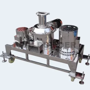


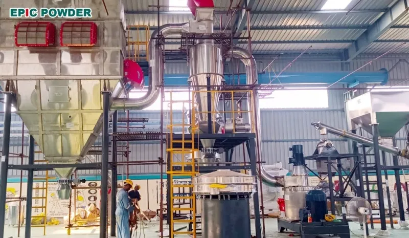
Partnership with Pakistan Customers: High-Quality Grinding and Classification Aluminum Powder Supply Solutions
Aluminum powder is widely used ...
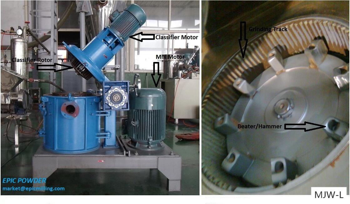
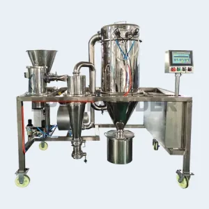
Malaysia Customer Use Air Classifier Mill for Buffer Salt Ultrafine Powder
Industries such as pharmaceuticals, food ...
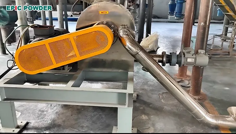
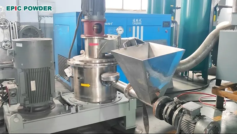
Air Classifier Mill Helps Thai Customer Achieve Efficient Coconut Shell Grinding
Customer Name: A Biomass Deep ...