Air Classifier Mill

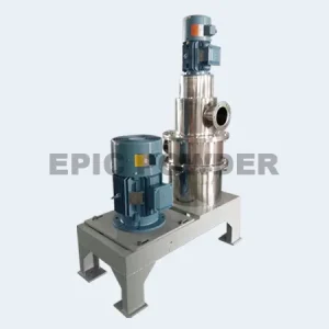
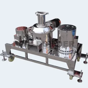
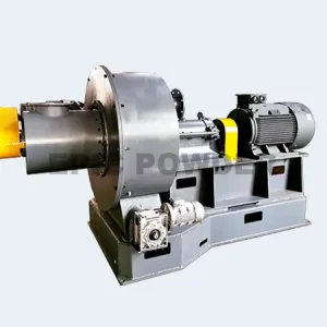
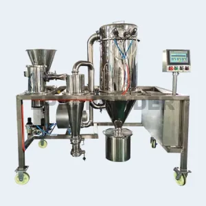
MJL-W Air Classifier Mill
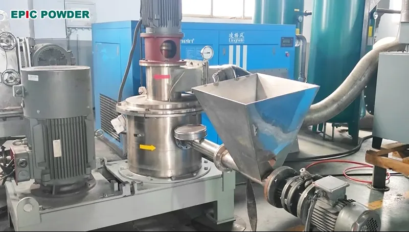
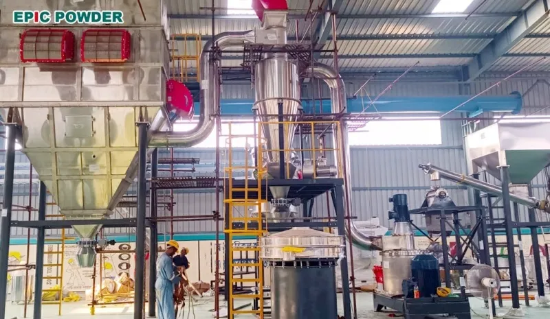
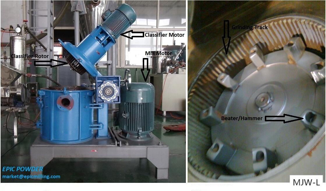
Get A Quote

    Please prove you are human by selecting the heart

    Contact Us
     
    • Double-sided hammer head structure design improves grinding efficiency.
    • Special feeding method, convenient for forced grinding.
    • External bearing, good heat dissipation, natural cooling or water cooling.
    • The structure of the side opening door is convenient for manual maintenance and cleaning.
    • Provide different construction materials according to different project needs, such as carbon steel, stainless steel, wear-resistant steel, and ceramic lining.
    • The overall steel structure base is conducive to the stable operation of the equipment.
    Operation

    The Air Classifying Mill requires air or gas for the conveying, size reduction and air classification of the product being processed. Air or gas is introduced to the  Air Classifying Mill via the main air inlet and the product inlet. As much as 30% of the total air volume can be introduced at the product inlet depending upon the application. Feed material is pneumatically conveyed under vacuum or mechanically conveyed by an auger, into the feed inlet of the mill along with the process air. Ideally, material is fed at a constant rate via a volumetric or gravimetric feeding device.

    After passing through the feed inlet, material enters the grinding zone. At this point, material comes in contact with the face of the rotating hammers, where impact takes place and the material is fractured into smaller particles. Situated around the perimeter of the grinding chamber is a “multiple deflector liner”. This component assists in slowing the peripheral velocity of the product and deflecting it back into the hammer path for more efficient impact and size reduction.

    The product is then conveyed upwards by the air stream through a shroud and baffle assembly that changes the direction of the product/air mixture while directing it to the classification zone. The shroud and baffle assembly also provides a separation of the mill internal area into two zones; a grinding zone and a classifying zone.

    Once the product enters the classification zone, the particles are presented to the rotating classifier wheel, where based upon size and density, the particles either pass through the classifier or oversize particles are rejected and flow back to the grinding zone for additional size reduction. The processed product/air mixture then exits through the mill outlet.

    There are two main parameters that are used to control and change particle cut point or maximum particle size; air volume through the mill and rotational speed of the classifier. The air flow through the mill generates a drag force to convey the particles to the classifier and the rotational speed of the classifier generates a centrifugal force that rejects the particles away from the classifier. When these two forces are equalized for a given particle mass, that particle has an equal probability of being accepted or rejected at the face of the classifier wheel. Based upon varying these opposing forces either through a change in air volume, or a change in classifier speed, the particle top size cut point can be controlled.

    •  
    Scroll to Top