
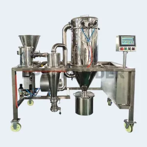


The Air Classifying Mill system is available in a wide range of sizes, materials of construction, finishes, pressure & vacuum designs, system configurations and control schemes.
Due to the Air Classifying Mill’s air to material ratio requirement, heat sensitive materials can be handled without product degradation. When milling hygroscopic materials, conditioned inlet air can be used to reduce moisture in the system. In high temperature drying applications, the bearing housing can be insulated and air purged to protect the bearings. The mill can also operate with chilled air for heat sensitive materials to prevent build up and for more efficient grinding.
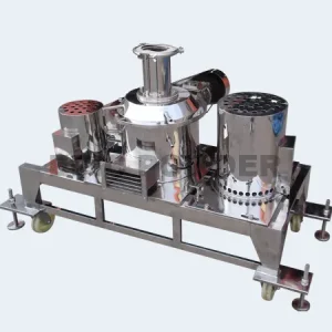
If your application requires frequent product changeover with cleaning in between, you may want to consider our Air Classifying Mill design. This mill incorporates several unique features that allow it to be quickly and easily disassembled and cleaned.
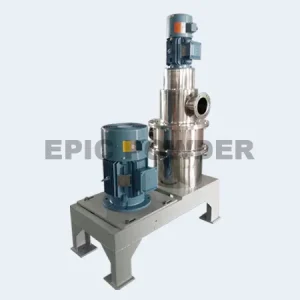
- Horizontal classification design, more suitable for ultra-fine powder production, performance comparable to German ZPS air classification mill.
- The unique grinding structure and classofying structure design realize the unique grinding effect.
- Special flow field design to avoid the accumulation of some materials with poor fluidity.
- The classifying apex cutting is more precise and the particle size distribution of the product is narrower.
- Easy to clean, suitable for the production needs of frequent replacement of materials.
Operation
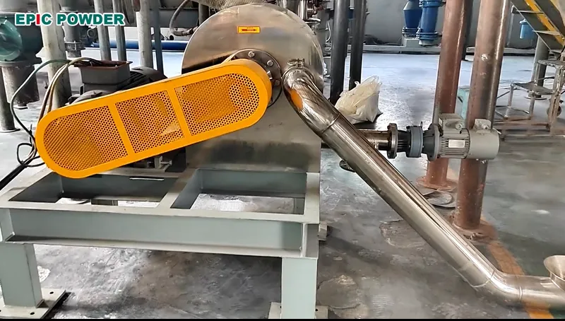
The Air Classifying Mill requires air or gas for the conveying, size reduction and air classification of the product being processed. Air or gas is introduced to the Air Classifying Mill via the main air inlet and the product inlet. As much as 30% of the total air volume can be introduced at the product inlet depending upon the application. Feed material is pneumatically conveyed under vacuum or mechanically conveyed by an auger, into the feed inlet of the mill along with the process air. Ideally, material is fed at a constant rate via a volumetric or gravimetric feeding device.
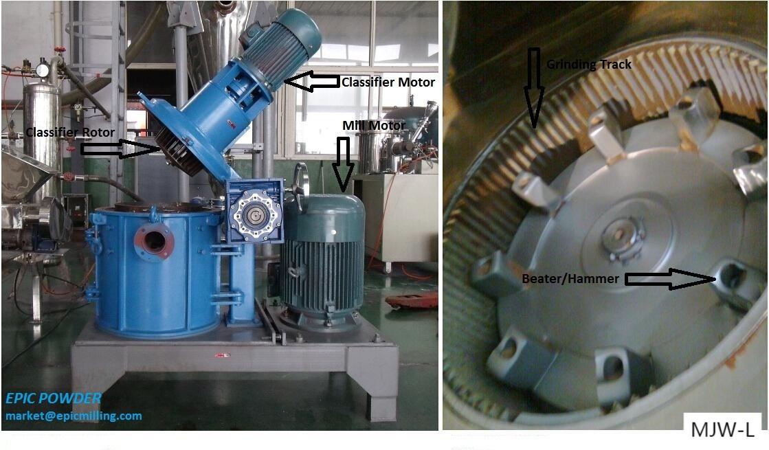
After passing through the feed inlet, material enters the grinding zone. At this point, material comes in contact with the face of the rotating hammers, where impact takes place and the material is fractured into smaller particles. Situated around the perimeter of the grinding chamber is a “multiple deflector liner”. This component assists in slowing the peripheral velocity of the product and deflecting it back into the hammer path for more efficient impact and size reduction.
The product is then conveyed upwards by the air stream through a shroud and baffle assembly that changes the direction of the product/air mixture while directing it to the classification zone. The shroud and baffle assembly also provides a separation of the mill internal area into two zones; a grinding zone and a classifying zone.
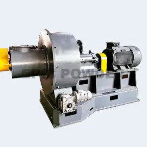
Once the product enters the classification zone, the particles are presented to the rotating classifier wheel, where based upon size and density, the particles either pass through the classifier or oversize particles are rejected and flow back to the grinding zone for additional size reduction. The processed product/air mixture then exits through the mill outlet.
There are two main parameters that are used to control and change particle cut point or maximum particle size; air volume through the mill and rotational speed of the classifier. The air flow through the mill generates a drag force to convey the particles to the classifier and the rotational speed of the classifier generates a centrifugal force that rejects the particles away from the classifier. When these two forces are equalized for a given particle mass, that particle has an equal probability of being accepted or rejected at the face of the classifier wheel. Based upon varying these opposing forces either through a change in air volume, or a change in classifier speed, the particle top size cut point can be controlled.
Parameter
| Model | 300 | 400 | 500 | 700 | 800 | 900 | 1000 | 1100 | 1250 | 1500 | 2000 |
|---|---|---|---|---|---|---|---|---|---|---|---|
| Motor Power(kw) | 7.5 | 22 | 30 | 45 | 55 | 75-90 | 90 | 110-132 | 160-200 | 250 | 355 |
| Rotating speed(rpm) | 7500 | 4800 | 4200 | 3000 | 2800 | 2350 | 2100 | 1920 | 1800 | 1500 | 1120 |
| Motor Power(kw) | 2.2 | 4 | 5.5 | 7.5 | 7.5-11 | 15 | 15-22 | 22-30 | 22-37 | 45-55 | 55-75 |
| Rotating speed(rpm max) | 4500 | 3250 | 3000 | 2920 | 2500 | 2200 | 2000 | 1800 | 1800 | 1500 | 1150 |
| Fineness (μm) | 5-300 | 5-300 | 5-300 | 5-300 | 5-300 | 5-300 | 5-300 | 5-300 | 5-300 | 5-300 | 5-300 |
| Capacity (kg/h) | 2-100 | 10-1000 | 15-1500 | 20-2000 | 25-2500 | 40-4000 | 45-4500 | 60-6000 | 75-75000 | 100-1000 | 15-15000 |
Send Us A Message
Related Caes
Bentonite Ultrafine Grinding Project in Greece
Partnership with Pakistan Customers: High-Quality Grinding and Classification Aluminum Powder Supply Solutions
Malaysia Customer Use Air Classifier Mill for Buffer Salt Ultrafine Powder